- -€23.44


ENSolarX Wi-Fi and management BMS ,of the photovoltaic system, solar inverter and energy storage.
The device enables remote control and configuration of parameters of three devices.
1. Allows you to control and configure the Solar Inverter.
2. Allows you to control and configure the parameters of the energy storage management system BMS (Battery Management System)
| Feature |
ENSolarX ver 5x Basic
|
ENSolarX ver 5x Full
|
ENSolarX ver 6x
|
ENSolarX ver 7x
|
|---|---|---|---|---|
| Communication with inverters via RS-232 and RS-485 | ✔️ | ✔️ | ✔️ | ✔️ |
| Communication with BMS via UART and RS-485 | ✔️ | ✔️ | ✔️ | ✔️ |
| Built-in Wi-Fi | ✔️ | ✔️ | ✔️ | ✔️ |
| Extended Wi-Fi range | ✔️ | ✔️ | ✔️ | ✔️ |
| Improved operational stability | ✔️ | ✔️ | ✔️ | ✔️ |
| Inputs for 3 temperature sensors | ❌ | ✔️ | ✔️ | ✔️ |
| External energy meter support | ❌ | ✔️ | ✔️ | ✔️ |
| Active balancer control output | ✔️ | ✔️ | ✔️ | ✔️ |
| 7 SSR relay outputs | ❌ | ✔️ | ✔️ | ✔️ |
| 0–10 V output for proportional heater control | ❌ | ✔️ | ✔️ | ✔️ |
| MODBUS for integration (e.g., Home Assistant) | ❌ | ✔️ | ✔️ | ✔️ |
| Configuration over Wi-Fi | ✔️ | ✔️ | ✔️ | ✔️ |
| Support for Wi-Fi relays – SONOFF | ❌ | ❌ | ✔️ | ✔️ |
| 4 additional outputs | ❌ | ❌ | ✔️ | ✔️ |
| Built-in converter for JK BMS RS-485, SEPLOS | ❌ | ❌ | ✔️ | ✔️ |
| Support for inverters: DEYE, SUNSYNK, SOFAR | ❌ | ❌ | ✔️ | ✔️ |
| Support for SRNE inverters | ❌ | ❌ | ❌ | ✔️ |
| Support for BRAUN POWER batteries with PYLONTECH BMS | ❌ | ❌ | ❌ | ✔️ |
| Support for DEYE SE-G5.1 energy storage | ❌ | ❌ | ❌ | ✔️ |
ENSolarX is a Wi-Fi module that allows monitoring and management of the photovoltaic system, solar inverter and energy storage.
The device enables remote control and configuration of parameters of three devices.
1. Allows you to control and configure the Solar Inverter.
2. Allows you to control and configure the parameters of the energy storage management system BMS (Battery Management System)
3. Allows you to control and configure the Rekuset recuperation controller.
4. Device supported by PC or Android phone apps.
5. In the last update, DALY BMS support was added and communication was improved
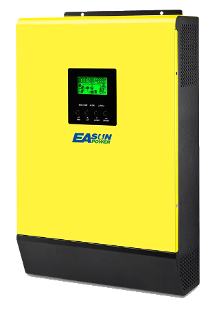
The ENSolarX device supports Hybrid Solar Inverters by Easun, Powland and BMSs by QUACC, JBD, ANT, DALY, JK (maximum number of cells 16)
The Inverter and BMS with the ENSolarX module are connected via RS-232 buses. The device has 2 separate inputs to operate the Inverter and BMS.
Description of the ENSolarX Management Program
The POWER STATUS tab displays data from the Rekuset driver, if one has been installed. If the RekuSet driver is not installed in the system, this tab will not be supported.
In the POWER STATUS tab, information on the status of atmospheric sensors and data on electricity consumption at a given moment as well as daily and monthly consumption charts are displayed. Data on consumption in this tab are taken from an external meter which sends data via pulse output to the Rekuset controller.
Possibility to control outputs, e.g. garden sprinklers.
The INVERTER tab displays current data from the Solar inverter and the BMS module, such as:
- Current production from Photovoltaic Panels.
- Current consumption.
- Voltage level in the network and at the output of the Inverter.
- Battery voltage.
- Load percentage.
- Inverter Heat Sink Temperature.
- Battery charge level.
- The remaining amount of energy in the batteries
- Charge level of individual cells
- Voltage difference between targets.
- etc..
The REKUSET tab displays current data from the Rekuset recuperation controller.
The OPTIONS tab is the configuration of settings, operating parameters of the Solar inverter and the BMS module.
- Configuring the network connection and the Internet connection of the EnsolarX module.
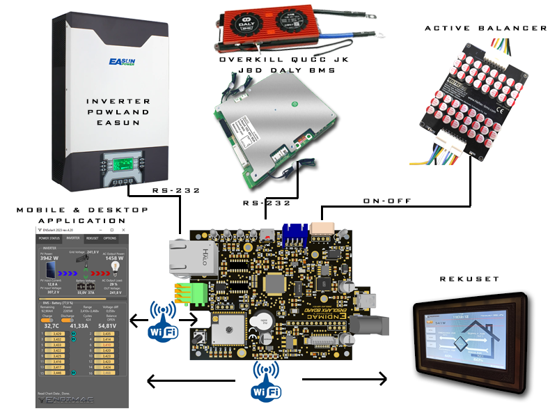
Below is a schematic diagram of the connections of individual modules.
ENSolarX does not require connection of all modules, it is possible to connect only one device for data analysis, i.e. only the inverter without BMS or BMS without inverter can be connected.
If a given peripheral device is not connected, only data from the unconnected device will not be displayed in the application, while the other components will communicate with the ENSolarX device
Obsługiwane Modele Falowników
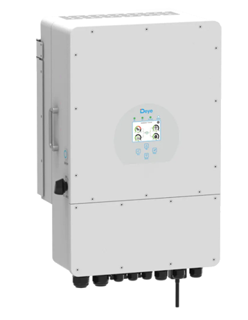
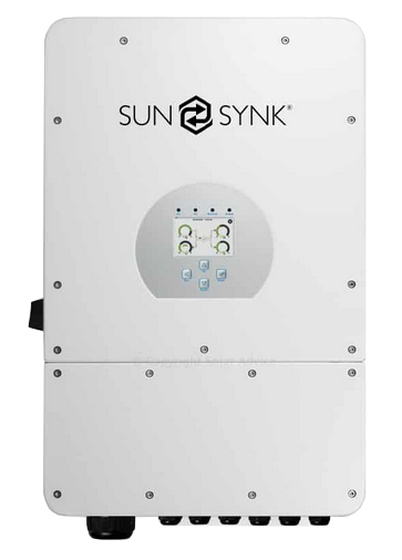
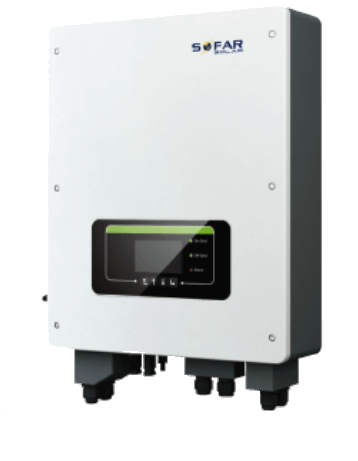
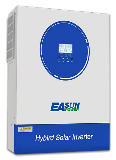
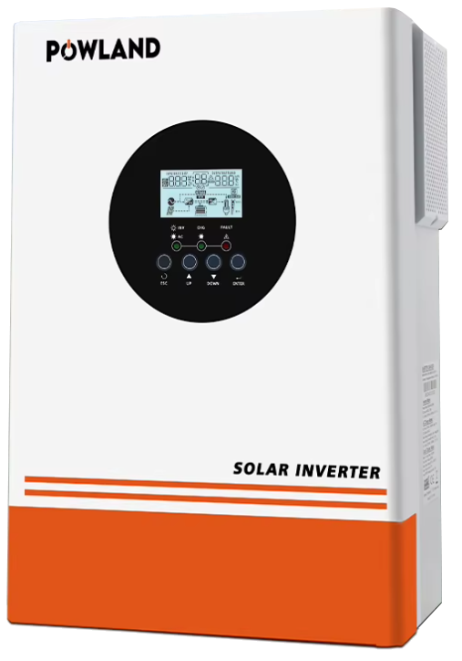
Deye 3-50KW LV & HV SunSynk 3-50KW LV & HV SOFAR IGrid SMG II 8KW-11KW ISOLAR SMG-III

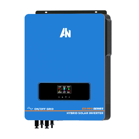

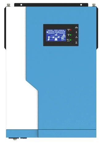
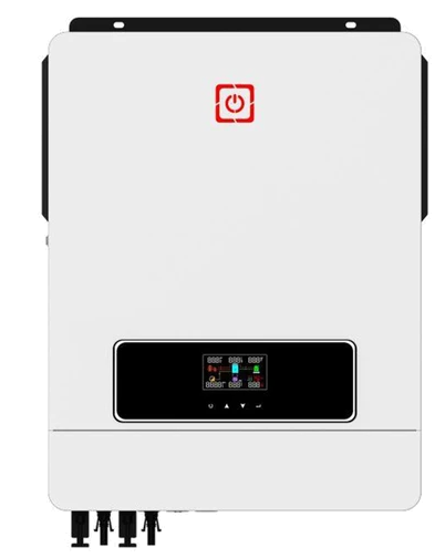
AN-EX-Pro-8200 MPS-V-3200 MPS-V-PLUS DAXTROMN
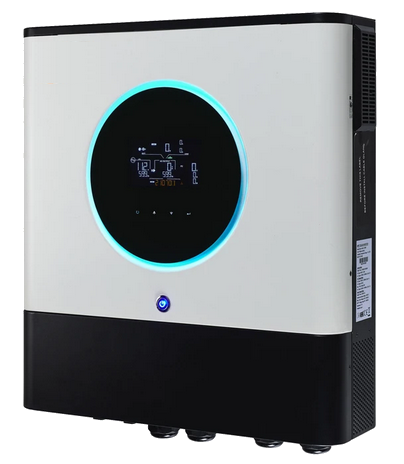
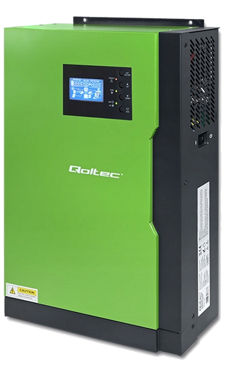
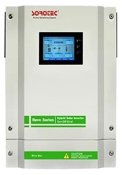
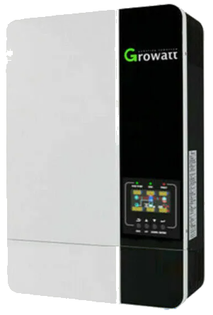
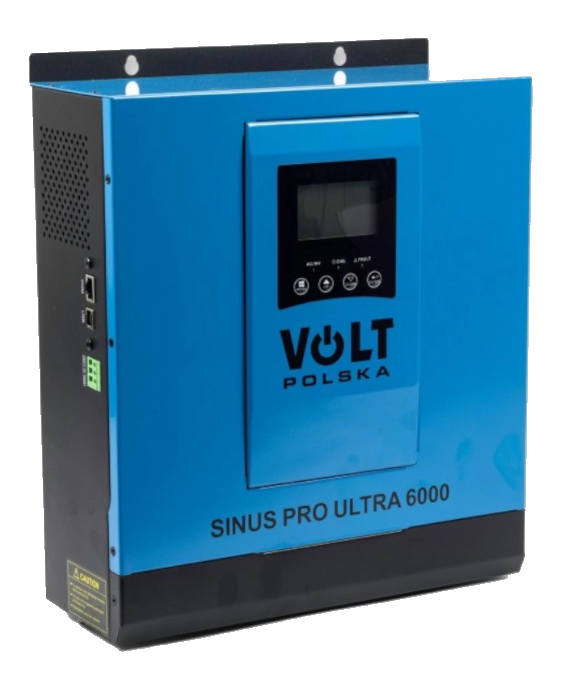
AXPERT MAX II QOLTEC REVO II GROWATT SPF-5000 VOLT
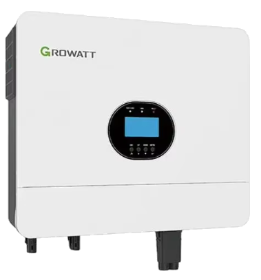
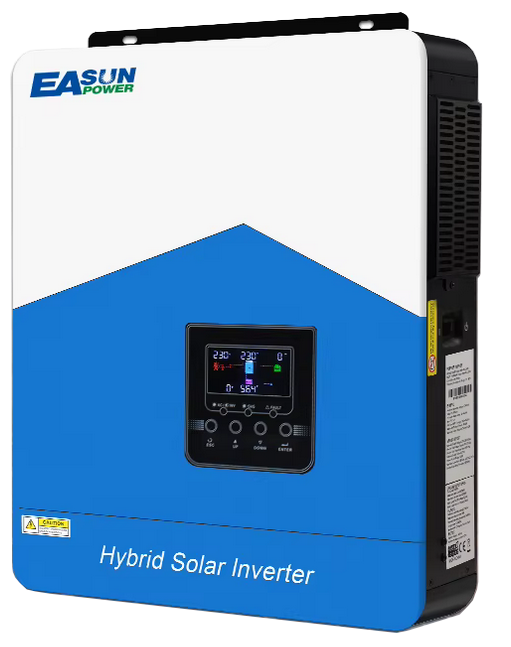
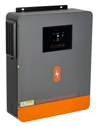
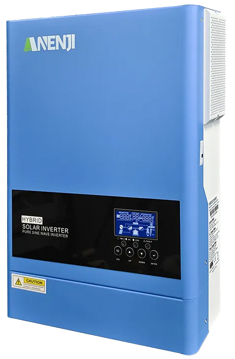
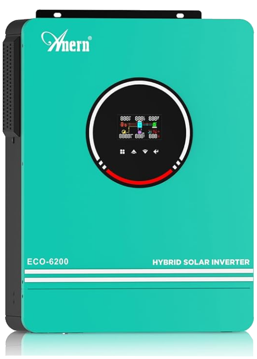
GROWATT SPF-6000 EASUN SMH-III PowMr ANENJI Anern
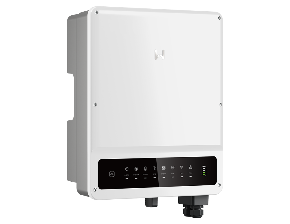
GoodWe SRNE
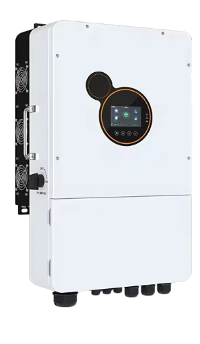
Connecting the Inverter to ENSolarX.
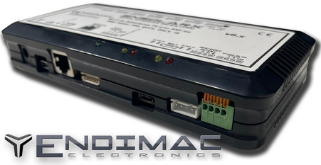
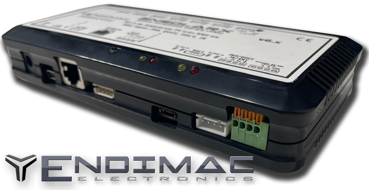
Depending on the inverter you have, the device should be connected via the DB9 9-pin connector or the RJ-45 connector. When ordering, please provide in the comments field information on which Inverter we will connect ENSolarX to attach a connecting cable to the DB9 or RJ-45 connector. The ENSolarX device communicates with inverters using RS-232 communication on the PI30 or Modbus RTU protocol. After connecting the inverter to the ENSolarX device, proper communication is confirmed by both RX TX LEDs located above the connector to the inverter on the ENSolarX board.
DALY BMS connection.
The BMS DALY should be connected to the ENSolarX device via the miniUSB socket, i.e. the miniUSB plug which is connected to the Bluetooth device should be connected to the miniUSB socket of the ENSolarX device. BMS should be automatically detected by ENSolarX as evidenced by both blinking RX and TX diodes above the miniUSB socket on the ENSolarX board

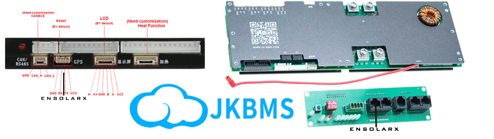
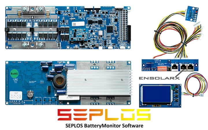
JK BMS, SEPLOS connection.
BMS JK to the ENSolarX device should be connected via a 4-pin socket marked in the picture below as RS485. descriptions of this socket differ in individual versions of these BMSs BMS should be automatically detected by ENSolarX, as evidenced by both blinking RX, TX diodes above the miniUSB socket on the ENSolarX board. When ordering, please provide in the comments field information to which BMS we will connect ENSolarX to attach a connecting cable to JK.
QUCC, JBD BMS connection.
BMS QUCC and JBD to the ENSolarX device should be connected via a 4-pin Bluetooth connector, i.e. disconnect the bluetooth board and connect this cable to the connector marked BMS on the ENSolarX board. The BMS should be automatically detected by ENSolarX as evidenced by both blinking RX TX diodes above the miniUSB socket on the ENSolarX board.

Connection of relays and heaters to SSR outputs (output 11)
and the active balancer.
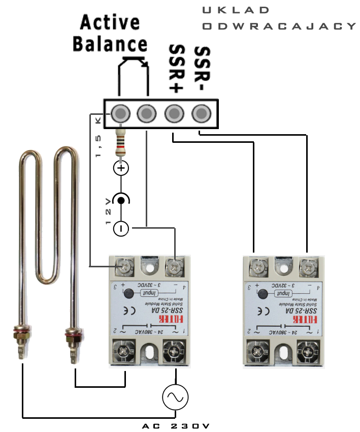
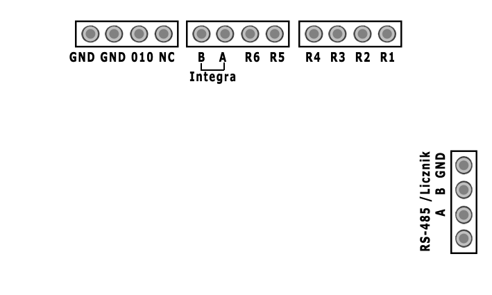
GND – Ground.
010 – Analog voltage output from 0 to 10V.
This output is used for smooth regulation, e.g., with an inverter, to redirect excess electrical energy to additional devices such as a heater.
NC – Not connected (unused).
A – B MODBUS output for integration with smart home management applications, such as Home Assistant.
R1 to R6 – 12V SSR relay outputs for controlling peripheral devices.
Connection of a bidirectional energy meter.
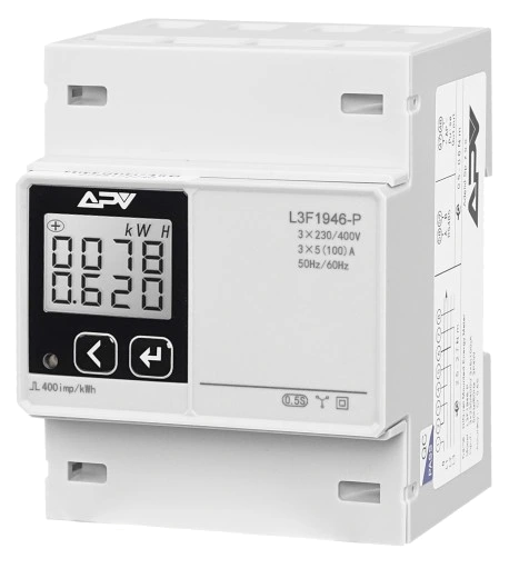 |
To connect an external energy meter for monitoring the electrical and photovoltaic installation, connect the wires labeled A and B to the corresponding terminals on the ENSolarX device, also marked as A and B. Only these two wires need to be connected. To monitor data from the device, go to the "NRG" tab in the ENSolarX application and select "Energy Meter" in the "Use Data From" field. As an example, the L3F1946 meter is recommended. The meter communicates using the MODBUS protocol. |
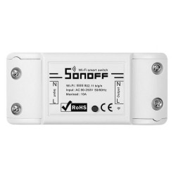
Connection of Sonoff relays.
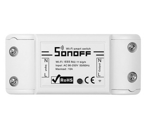 |
ENSolarX now supports controlling popular Sonoff relays, enabling remote switching of devices on and off via a convenient application. With Sonoff integration, the system offers even greater flexibility for home and industrial automation. Managing relays has now become simpler, seamless, and accessible from anywhere. Thanks to this integration, users can remotely control devices connected to relays, making automation in homes and industries easier. Control is performed using a user-friendly application, allowing devices to be turned on and off at any time and from any location. ENSolarX with Sonoff is the perfect solution for those who value simplicity and efficiency. Cooperation with Sonoff relays opens up new possibilities, providing full control over energy management. |
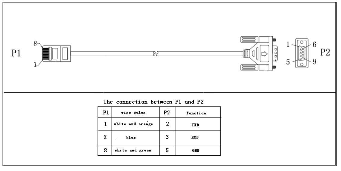
If the inverter is equipped with an RJ45 connector, such a cable is included in the set. However, if the inverter is equipped with a DB9 connector, such a cable can be made manually. Below is the wiring diagram for some inverters with a DB9 connector.

Data sheet
Specific References
ENSolarX Wi-Fi and management BMS ,of the photovoltaic system, solar inverter and energy storage.
The device enables remote control and configuration of parameters of three devices.
1. Allows you to control and configure the Solar Inverter.
2. Allows you to control and configure the parameters of the energy storage management system BMS (Battery Management System)